LEGACY INFORMATIO - Medium Power 144 MHz Amplifier using the Y799 tube.
The information contained here is probably of little value now. I was intending buiding a conduction cooled Y799 amplifier, but transistors have come along dramatically in performance, and there is no point in building such a project now.
One amplifier, based on the Eimac Y799 tube (conduction cooled version of the 4CX250B) is under construction. This will be used to drive the YC156/3CX5000A7 amplifier, also under construction. The amp should be able to use a Y808 too. I don't have a Y808 data sheet, but am told its very similar to the Y799. If anyone has a Y808 data sheet, please let me know by email This Y799 (or Y808) amplifier should produce about 250 to 300 W in class AB1 at reasonable intermodulation performance. The amplifier has a large (0.2 deg C/Watt, weighing 15 kg) heatsink, and should keep the tube below the maximum 250°C at 200 W dissipation. 200 W dissipation should be sufficient for about 250 W of output, which should be adequate to drive the YC156 or 3CX5000A7
The screen and grid supply will use the G3SEK tetrode boards. The heater supply will be regulated with a 5A 3-terminal regulator.
 |
The Y799, is similar to the Y808 I believe. Any hard data on either tube would be appreciated. |
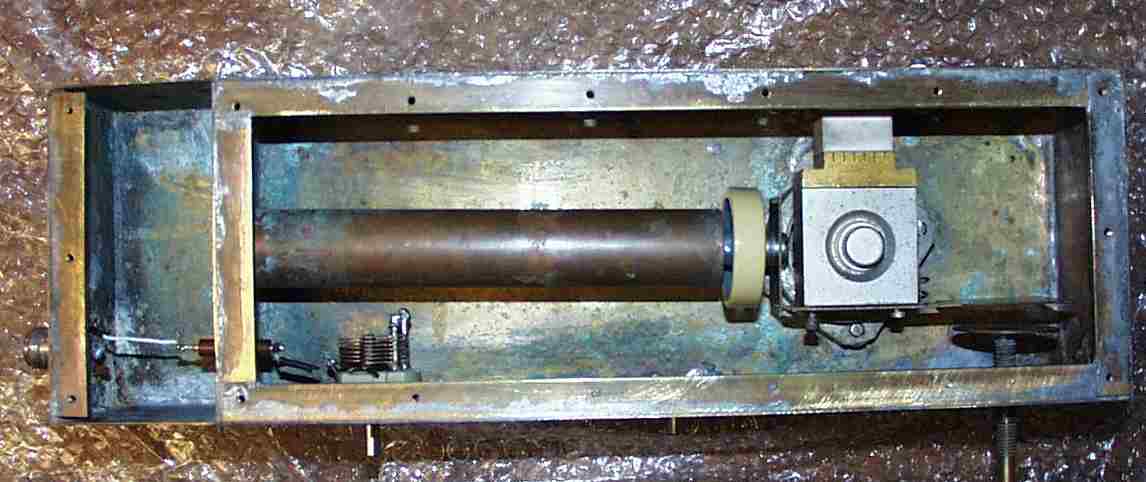 |
This shows the top view of the amplifier (click on the image for a higher resolution version). The output will be coupled from the line inductively - note the variable loading capacitor on the left of the anode region. |
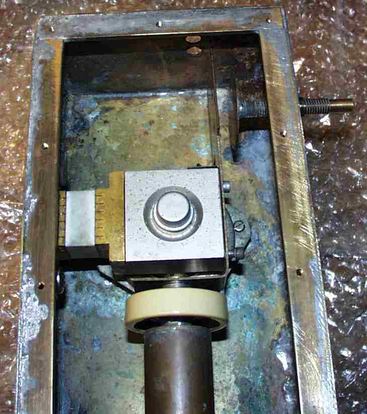 |
Here is a close up of the anode of the tube. Note the square anode of the Y799 tube. The heat sink adapter has a gold coloured block mounted mounted on the tube with thermally conducting paste and a while BeO link to conduct heat to the heatsink which will be attached to the rear. Note the anode line and tuning capacitor. The anode tuning control consists of a disk attached to shaft, which has an M6 thread on it. This moves back and forth as the shaft is rotated. A locking nut, which is not installed, will be used to stop the tuning control shorting out the HT supply. A small microswitch will be held closed normally by something soldered to the anode with a low melting point solder. Should the anode get too hot, the link will melt and shut the amplifier down. |
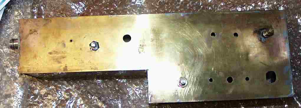 |
In the side view, we can see the there are is a compartment below the tube where the input section of the tube is located. |
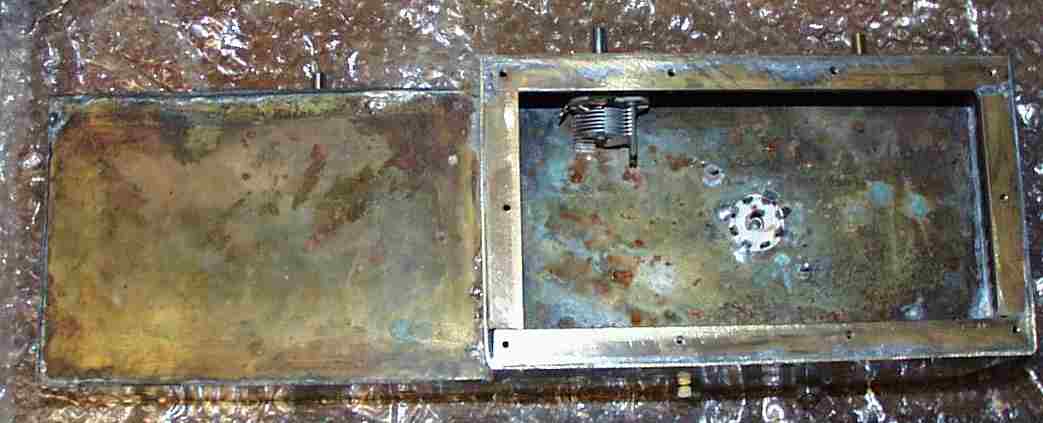 |
He we can see the Eimac SK-660A base, which is made from white BeO to conduct heat away from the tube. The grid tuning capacitor can also be seen. |
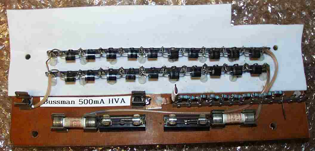 |
The high voltage rectifier stack consists of 10 P600M 1000V, 6 A rectifier diodes in series. There are two fuses in series on the AC input to the rectifiers, as I'm not quite sure what fuses to use. On the DC output will be a 500 mA high-voltage fuse, made by Bussman. The PTFE sheet shown is to insulate this from other components in the amplifier. |
