High Power 144 MHz Amplifier using the Eimac 3CX5000A7 or YC156
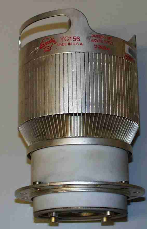 |
Apart from the Y799/Y808 driver amplifier, I have also under construction a somewhat bigger project using either an Eimac 3CX5000A7 or YC156 triode. A YC156 is shown to the left, but the 3CX5000A7 looks identical. Click on the image for a higher resolution larger version. The 3CX5000A7 was offered to me first, and work started. Eimac tell me the tube is rare, so my chances of finding a second are small. Then there was a large number of YC156's tubes available on the second hand market. These are mechanically identical, but electrically different, from the 3CX5000A7. Electrical difference include a higher heater voltage (15 V for the YC156, 10 V for the 3CX5000A7), and somewhat higher inter electrode capacitance's. |
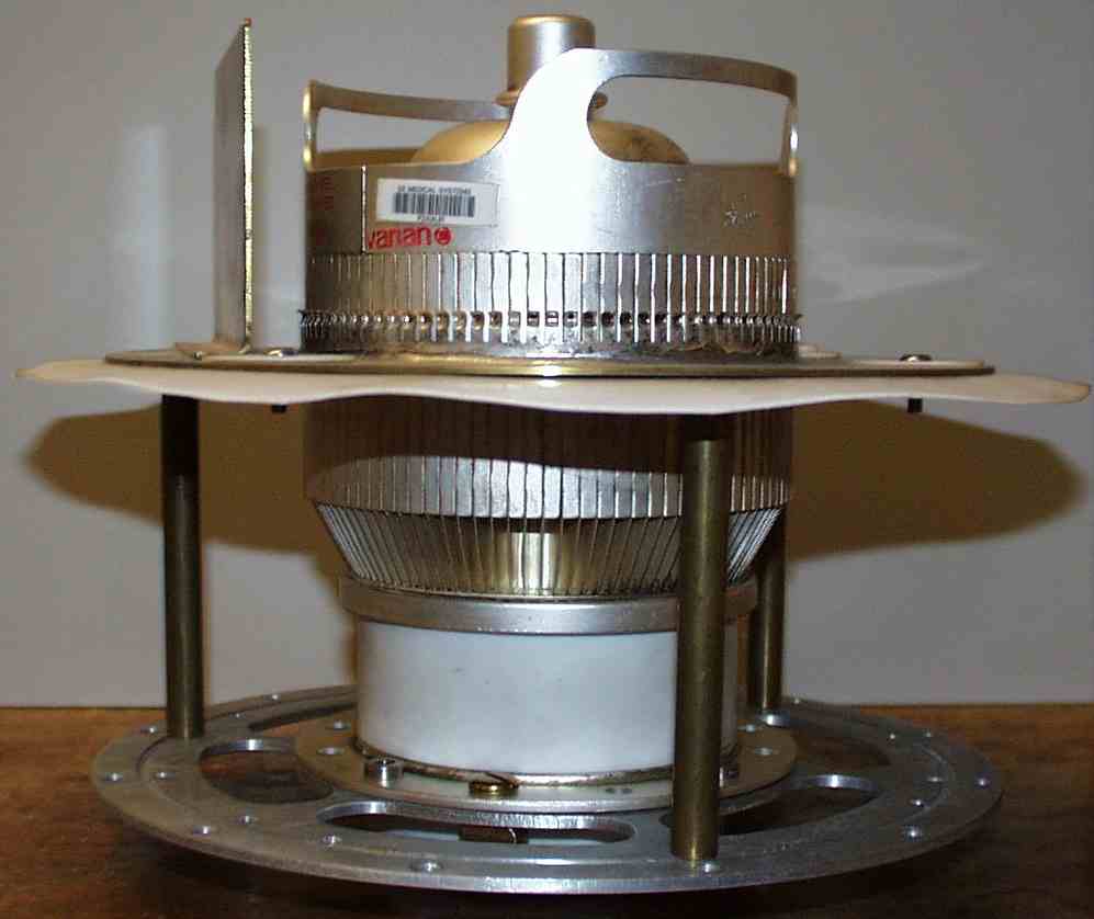
The amplifier is being built using a chassis welded from 1" angle iron. 2 mm aluminium panels bolt to this with lots of M6 screws. The fan sits on the back. The fan, a rather over-speced VBL9 centrifugal device from Air Control Industries Ltd was purchased new. I ordered a bigger fan than needed, on the hope it would do an Eimac 4CX10,000 tube, had the original 3CX5000A7 been non-functional. It produces about 1000 cfm through the tube (estimated from the back pressure and the fan manufacturers flow/pressure curve), but make a lot of noise. The fan takes 10A when running from the mains, and easily blows a 13A fuse every time at start-up.
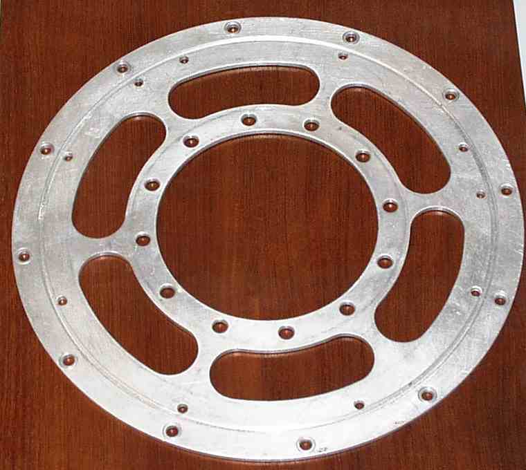 |
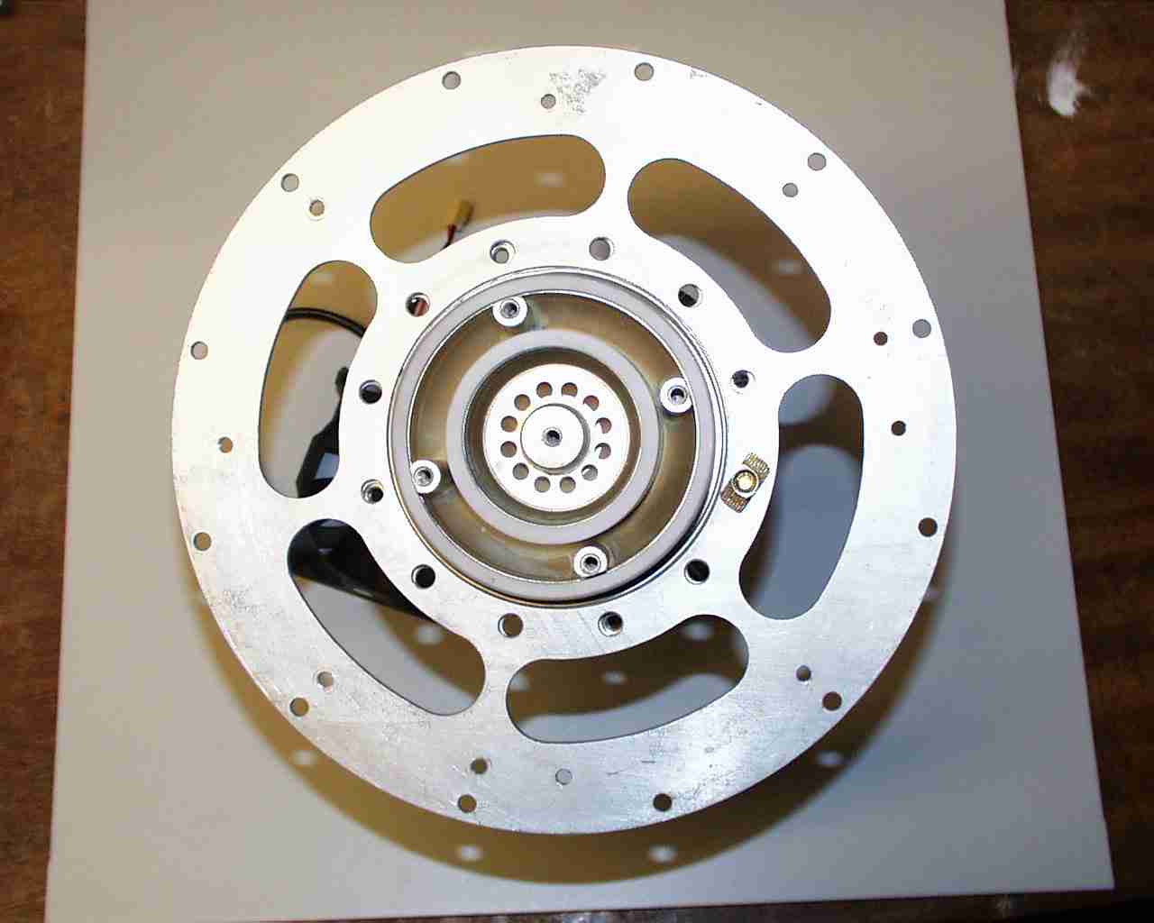
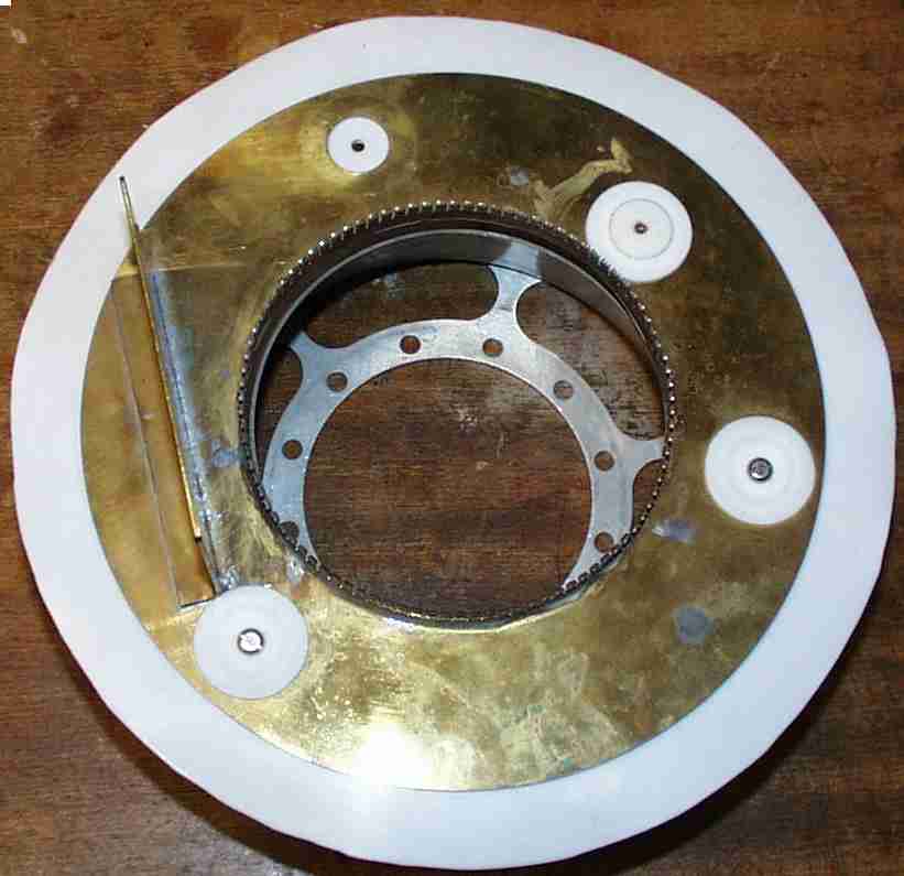
Neither tube requires a socket. The tube is attached to the chassis by the grid ring, but some slots are needed outside the tube to allow air flow. A plate was made for this, which has 3 rings of circular holes and one ring of slots. The inner ring of 12 holes is used to attach the tubes grid ring. The 6 slots outside these 12 holes are for airflow. Outside of this are a ring of holes to mount the chimney and outside these are a ring of holes to attach the plate to the chassis. Although not very clear from the small image, a ring is milled all away around the plate, for the chimney to fit in. Click on the image to the left for a higher resolution version. You can also see an underside view of the tube attached to the cooling plate with one screw. |
 |
The anode resonator is unconventional. There are 3 anode lines, each supporting a plate attached to the anode with fingerstock. Above this plate is a second plate, separated from the first with 1 mm PTFE sheet. On this upper plate will be two capacitor stator plates - one for the tuning capacitor (shown to the left) and another for the loading capacitor, which is not installed yet. On the right is an underside view of the anode line. Again, to see a higher resolution images, click on the images. | 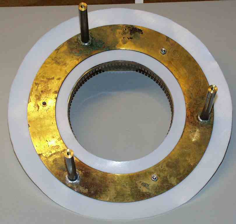 |
The heater supply for this amplifier uses the National Instruments LM723 voltage regulator IC, as a constant voltage (but current limited) supply. It uses several Siemens BUZ100 (Vds=50 V, Id =60A) FETs as external pass transistors.
The anode supply has not been built yet, although I do have access to a 3kV 2A supply built by G8WYI for a 2m amplifier using a pair of 4CX1000A's in push-pull grounded screen - an amplifier that has never worked well. Anyway, this HT supply will probably be used to initially test the 3CX5000A7/YC156 amp, before I go and get a transformer wound for 5 kV or so of DC.
The output from the amplifier will be taken via a directional coupler I spent about a week (full time) making. This has a pair of 7-16 connectors for input and output connections and four SMA connectors for the coupled lines. The output from the amplifier is 7-16, the input N. The RF relay uses SC connectors, which should just about be upto the job. The RF is coupled from the amplifier to the directional coupler using a piece of air spaced coax, I managed to scrounge from. Andrews
The input section has not been built yet, although have simulated some possible designs on computer.
I had considered using a microprocessor to control the amplifier. I even went as far as to purchase a small micro controller (Tern V104). This has a NEC V25 8086 compatible microprocessor, 11 channels of ADC (using the Texas Instruments TLC2543), 4 channels of DAC (using Maxim MAX 536), watchdog (using Maxim MAX691), LCD display (using Hitachi HD44780) etc. I have got as far as to write the software (in C) and put the micro controller in a rather expensive aluminium box, with the hope of keeping the RF out from the micro, and the noise from the processor away from the receiver. The program is written in such a way that that tube should be protected from high drive, excessive anode current, excessive or low heater voltage etc. Whether or not this gets finished is another matter.
Interesting letters and e-mails.
Here is an email from Eimac about the YC156, and pulsed tubes in general, which may be of interest. It shows there is no problem using pulsed tubes in CW/SSB service.
In an e-mail that I received from Eimac, they state that while the 3CX5000A7 is shown on the data sheet to be suitable for FM service, they do that advise this, due the the failure rate that has been observed in practice. Given so few people buy the 3CX5000A7, they have not (or at least had not at the time) updated the data sheet to reflect this.
I had an interesting email from someone who used to use YC156 tubes professionally in amplifiers they built. He said they once took a YC156 and run it up so that it produced 40 kW of RF output. The tube was run like that for 4 days ! At the end of the 4 days the tube had blackened considerably, but when put back into a amplifier, it met their specs.
Here is a copy of a letter from Eimac about the 3CX5000A7 - this was before I got any YC156 tubes. It included a copy of an amplifier for 2m using the 3CX5000A7, but it was impossible to follow.I gave up, as the drawings are so poor. I've not bothered scanning that.
If you wish to discuss this amplifier, e-mail me me an e-mail.
Estimated date of completion
I'm not that brave, as time for this project is quite restricted. I used to blame doing Ph.D, but now I need another excuse, since I got my PhD back in 1999.
